|
P dV's Engine Test Cell Design, Installation, and Instrumentation Capabilities Select from the list below:
|
| • Engine Dynamometer Test Cells |
| • Chassis Dynamometers |
| • Component Test Stands |
|
• Turbocharger Test Stand
|
|
|
|
P dV Provides Engine Test Cell Specifications, Design, & Installation Support
|

|
• Test Cell Specifications
P dV has experience in designing, installing, and instrumenting test cells for testing of internal combustion engines.
Whether for performance, emissions, or durability testing, P dV's experience includes:
|

|
• Test Cell Design & Installation
From small single cylinder engines to large, stationary in-line six cylinder engines. From water-cooled to air-cooled. From cars to motorcycles. From gasoline to natural gas fuels, with alcohols and exotic racing fuels in-between. P dV has experience designing and installing a wide variety of engine test cells.
|

|
• Durability Testing
P dV has set up test cells for durability testing of engines, including the test cell systems required for sustained engine testing, the data acquisition and control system to monitor and control test conditions, and the test programs themselves. P dV has specified and installed engine health monitoring systems to keep track of engine changes during testing. This includes the measurement of oil consumption, fuel consumption, engine blowby, and periodic checks of compression and leak-down rates. Oil sampling and analyis for wear metals, in combination with One such test monitored engine bearing health with proximity probes measuring crankshaft run-out in two axes 90 degrees apart. Safety limits were set and monitored by the control system to shut down the engine if limits were exceeded. Durability testing often includes the teardown and inspection of engine components at periodic intervals and/or at end of test. P dV has experience in analyzing engine components for wear and for failure analysis.
|

|
• Custom Engine/Dynamometer Drivetrains
P dV has experience setting up not only dynamometers and engines, but the all important link between the two: the drivetrain. Simply connecting the two with a plain driveshaft is often ignoring critical shaft speeds that can destroy not only the driveline, but expensive dynos and engines.
P dV has specified:
|
|
|
|
|
|
P dV Has Conducted Chassis Dynamometer Testing
|

|
• Automotive and Motorcycle Chassis Dynamometer Testing
P dV has set up test programs for testing of vehicles and motorcycles on chassis dynamometers. Once such test had the operator drive the first portion of the EPA cycle while cold start emissions were collected for evaluation of emission reduction strategies. P dV purchased a Clayton twin-roller chassis dynamometer, with a water brake style power absorber, P dV is refurbishing and upgrading the dynamometer system by improving the water brake cooling system, and adding a PC computer-based data acquisition and control system.
|
|
|
|
|
|
Component Test Stands
|

|
• P dV Has Experience With Component Test Stands
P dV has used component test stands to test individual engine parts or subsystems. Instead of more expensive egine tests, the component test stand can produce test reasults in a faster, less expensive manner.
|
|
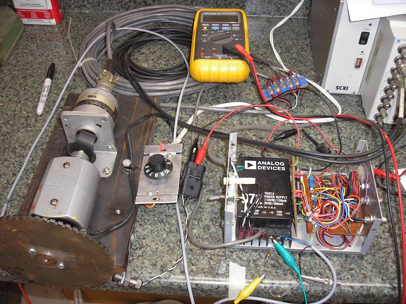
• Bench Testing of Components
Typically, using the engine mounted in a test cell is not the ideal test bed to be developing an encoder application, especially when the engine is air-cooled and fuel is expensive. Then there are engine operators hours spent, and other tests that are being pushed aside. P dV solved the problem by using a simple test bench toothed wheel to simulate the engine's toothed flywheel, allowing development of the hardware and software required to trigger off of the flywheel teeth and provide event-based capturing of cylinder pressure. The variable-speed electric motor has a standard optical shaft encoder mounted on one end, and a toothed wheel mounted on the other. This arrangement not only allows for testing of various types of sensors to read the toothed wheel, but also allows comparison to a known standard.
|
|
|
|
|
|
P dV Has Experience with Turbocharger Test Stands
|

|
• Turbocharger Testing: test cell design and installation
A test cell was designed for testing of automotive turbochargers independent of the engine on which they are normally installed. Engine installations are
expensive to setup and maintain, and are not cost effective for testing of turbochargers. The design criteria for the test cell were:
|
|
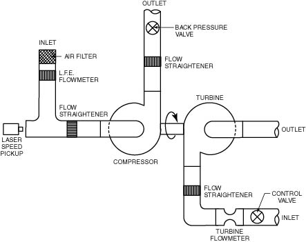
• Turbocharger Testing: test cell instrumentation and data acquisition
The design of the turbocharger test cell required special instrumentation for obtaining turbo wheel speed. A laser speed pickup sensor was used to measure
the rotational speed of the compressor by aiming the laser at a reflective section applied to the compressor hub. The system was able to detect wheel speed
when aimed through a window mounted in the intake tract. This was required since air flow had to be accurately measured at the compressor inlet. A Laminar
Flow Element (LFE) air flow meter was installed in the inlet to the compressor for that purpose. Throttles mounted on the compressor outlet and turbine
inlet controlled flows and pressure ratios, thereby controlling wheel speeds. The throttles were remotely controlled from the operators console. A large
turbine flow meter measured turbine inlet mass flow when required. Pressures and temperatures measured at inlets and exits to both turbine and compressor
were used to calculate flow conditions and corrected parameters.
|
|
|
|
|